Du befindest dich im Archiv dieses Weblogs. Für aktuelle Informationen besuche uns bitte auf technikkultur-erfurt.de
If you, like I did, want to use a graphical tool to enter state machines and, like I did, get convinced to use proper event driven software development when programming your Arduino to get the best battery life possible and are, like I am, way to lazy to program all that event queues and dispatching yourself you may, like I did, stumble upon the Quantum Leap Framework. It sounds good on paper, being open source but still rather professional and mature.
The framework is portable to Arduino devices and there even is a special release for Arduino and da rather good application note serving as a tutorial.
If it would just work.
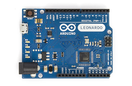
If you are, like I am, owner of an Arduino Leonardo, your first build of the example project „blinky“ from within the QM Modelling Tool will greet you with a lot of fails.
Here is how I solved it:
TIMER2_COMPA_vect, TCCR2A and others not declared
warning: 'TIMER2_COMPA_vect' appears to be a misspelled signal handler [enabled by default]

error: 'TCCR2A' was not declared in this scope

...
and other undefines symbols like TCCR2A and WGM01.
These are predefined symbols for registers, constants and functions set in the AVR library to control the interrupt system, timers and watchdogs of the CPU.
The Leonardo is based on the ATmega32u4 CPU in contrast to the UNO (ATmega328P) or the Mega (ATmega1280). This also means that the interrupt system is quite different.
| Board | Digital Pins Usable For Interrupts | Timers |
|---|---|---|
| Uno, Nano, Mini, other 328-based | 2, 3 | 2x8bit (0,2), 1x16bit (1) |
| Mega, Mega2560, MegaADK | 2, 3, 18, 19, 20, 21 | 2x8bit (0,2), 4x16bit (1,3,4,5) |
| Micro, Leonardo, other 32u4-based | 0, 1, 2, 3, 7 | 1x8bit (0), 2x16bit (1,3), 1x10bit@64MHz (4) |
| Zero | all digital pins, except 4 | 5x16bit, 3x24bit |
| Due | all digital pins | 9x32bit |
So the Leonardo has only one 8bit timer/counter and as the indexing is fixed, it is missing Timer2.
There are architecture-independent library functions in the Arduino library to configure them for PWM duty cycles and other things, but most example code I found (and so does the QM example) writes to the hardware registers directly.
As Timer2 is missing, we need to replace all symbol names to reference Timer0 instead. Luckily, they use a clear naming scheme where we only need to replace the number literal 2->0 (eg. TCCR2A->TCCR0A).
BEWARE! Timer0 is internally used for functions like delay(), millis() and is even re-configured by libraries like ’servo‘. If you use these in your code, you have to switch to a 16bit counter like Timer1, which is probably more complicated due to different configuration.
ASSR not declared
error: 'ASSR' was not declared in this scope

error: 'AS2' was not declared in this scope
Same reason as above. The ATmega32u4 is missing the possibility to use an external clock input for the timers. So switching between internal and external is not needed. The register ASSR does not exist. Comment it out.
USB_VID not declared
error: 'USB_VID' was not declared in this scope

error: 'USB_PID' was not declared in this scope
When building from inside the QM Modelling Tool, all Arduino libs will get compiled from source again. The USB lib will fail due to undefined symbols. The USB Vendor- and Product-ID seems not to be set in the code, but supplied as pre-processor define when calling the compiler. The Android IDE handles this for you, the QM tool does not.
Open the External Tool Settings, select the ‚build‘ tool and add „USB_PID=0x0036 USB_VID=0x2341“ (with the quotes) to the end of the ‚Argument‘ field.
__cxa_guard_release link error
undefined reference to __cxa_guard_acquire'__cxa_guard_release'
undefined reference to
This function was once implemented as a stub in the Arduino libs. Instead a compiler switch is now used to circumvent its usage. Again, the Arduino IDE handles this for you, the QM tool does not.
The g++ compile switch is -fno-threadsafe-statics (you can find it in the platform.txt definition file in the <Arduino_Program_Dir>\hardware\arduino\avr folder).
You need to add it to the switches already defined for the QM Tool in the file <Arduino_Project_Dir>\tools\scripts\build_avr.tcl. Search for set CXXFLAGS, line 102 in my file.
This will make the example compile and that is where I am now. So I can’t guarantee that it actually ‚works‘ by now or even that it ‚works as intended‘. Stay tuned for an update.
(article image CC 3.0 BYSA from arduino.cc)

Ist dafür jetzt nach erfolgreichem fork ein Elternprozess.
- [Veranstaltungsupdate] CTF -Vortrag heute als Videokonferenz - 15. März 2020
- [Veranstaltungsupdate] CTF als virtueller Vortrag - 13. März 2020
- [Veranstaltungshinweis] CaptureTheFlag – Hacking for sports - 10. März 2020